
P500 3D Measurement Scanner for Multi-Range Industrial Inspection
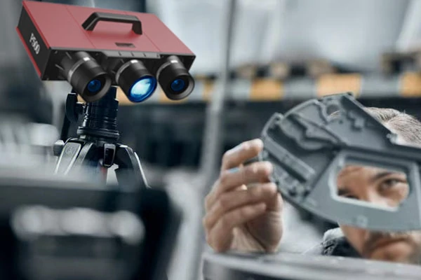
A multi-range 3D measurement scanner designed for manufacturing teams that inspect different part sizes. Configure your measurement platform with selectable optical measuring ranges without limiting every project to a single fixed field of view.
One 3D Measurement Scanner for Different Part Sizes
A quality lab may inspect a 60 mm precision component in the morning and a 500 mm mold in the afternoon. A fixed measuring range forces a compromise between coverage and detail. P500 solves this by offering multiple selectable ranges on one platform.
Small Precision Parts
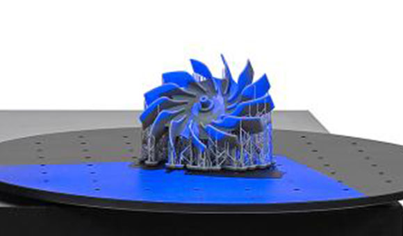
For gears, connectors, and small machined parts requiring high data density to capture fine edge details and narrow grooves.
Medium Industrial Components
For housings, toolings, and mold inserts where balancing scan speed and dimensional accuracy is critical for routine inspection.
Larger Components
For molds, castings, and industrial housings requiring a larger field of view to efficiently cover expansive surface areas without excessive repositioning.
Standard configuration allows you to choose 3 measuring ranges from 50×38 mm up to 400×300 mm.
Send Us Your Typical Part SizesChoose the P500 Measuring Ranges That Match Your Product Family
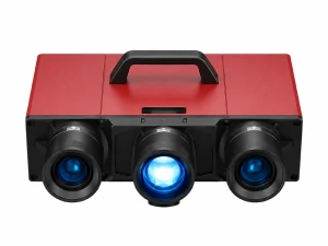
The P500 3D measurement scanner offers five distinct optical ranges. By selecting three ranges, your engineering team can adapt the platform to specific part dimensions and tolerance requirements.
- Object Size:
- 5–100 mm
- Point Cloud Acc:
- 0.02 mm
- Object Size:
- 50–200 mm
- Point Cloud Acc:
- 0.04 mm
- Object Size:
- 100–500 mm
- Point Cloud Acc:
- 0.08 mm
- Object Size:
- 150–700 mm
- Point Cloud Acc:
- 0.12 mm
- Object Size:
- 200–1000 mm
- Point Cloud Acc:
- 0.15 mm
Standard P500 configuration: choose 3 of the 5 measuring ranges based on your production needs.
Ask an Engineer to Select My 3 RangesMatch Measuring Range to the Detail You Actually Need
A larger field of view speeds up coverage, but will you lose the small features you need to inspect? A fixed measuring range forces a compromise. The P500 multi-range 3D scanner allows you to match the physics of optics to your inspection requirement.
- Smaller Field of View (e.g., 50×38 mm): Provides denser point clouds (0.02 mm accuracy) for fine features and tight tolerances.
- Larger Field of View (e.g., 400×300 mm): Reduces the number of scan shots needed to cover large molds or castings, improving workflow speed.
Choose the measuring range based on part size + feature size + tolerance + workflow.
Capture the Surface, Not Just Individual Measurement Points
Traditional Contact Measurement
Calipers and traditional CMMs remain highly useful for specific dimensional tasks and tight-tolerance prismatic features. However, inspecting complex freeform components, impellers, or curved castings can require numerous individual measurement points, making the process slow and incomplete for overall surface evaluation.
Full-Field Non-Contact 3D Measurement
The P500 captures dense, non-contact surface data. A single scan acquisition provides millions of coordinate points, creating a complete digital twin. This full-field surface data complements dimensional inspection workflows where understanding the complete geometry, deviations, and profiles matters.
Reduce Data-Capture Time in Repetitive Inspection Work
Slow inspection can become a QC bottleneck. The P500 accelerates the data acquisition phase with high-speed optical projection and capture.
Note on Workflow Speed: While single-frame capture is under 1 second, complete inspection time depends on the number of scan views required, part geometry, alignment complexity, specific measurement tasks, and reporting requirements. The P500 reduces the time spent acquiring data so engineers can focus on analysis.
How P500 Captures 3D Surface Data
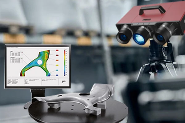
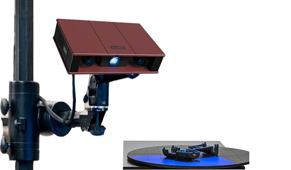
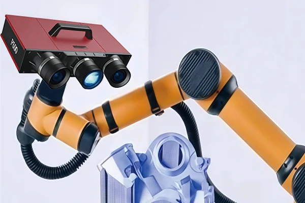
The P500 is a stationary blue-light structured-light optical scanner designed for controlled, precision-oriented measurement workflows.
Project Blue Structured Light
Capture Surface Geometry
Calculate 3D Coordinates
Build Point Cloud / Mesh

Engineering Consideration: Surface Conditions
Reflective, dark, or changing ambient conditions can affect optical scanning. While the P500 uses advanced blue-light technology and data-processing algorithms to improve acquisition, actual scan quality depends on surface reflectivity, color, finish, and geometry. Highly reflective or transparent surfaces may require parameter adjustments or appropriate surface preparation (scanning spray) for optimal results.
P500 Hardware + In-House STScan Software
Scanner hardware and software are developed as one connected STScan workflow, reducing the fragmentation of moving scan data through too many software packages.
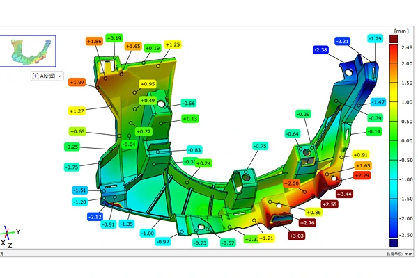
STScan Scanning & Inspection Software Interface
Exported data can be used in compatible downstream engineering workflows involving industry-standard software such as UG, CATIA, and Geomagic.
From 3D Scan to Dimensional Inspection
The P500 3D inspection scanner translates physical parts into actionable quality data.

Old / Legacy Physical Part
Mesh to CAD Reconstruction
Measure Parts Without Original CAD Drawings
When dealing with legacy components, replacement parts, obsolete tooling, or imported parts without drawings, the P500 captures the physical geometry. It outputs standard STL, OBJ, or PLY files, ready to enter your downstream CAD reconstruction workflow.
P500 or T500: Which STScan Scanner Fits Your Workflow?
Compare our stationary optical measurement platforms based on your production variation.
STScan T500
- Similar part sizes
- Dedicated inspection station
- Repeatable product family
- One selected measuring range
STScan P500
- Different product sizes
- Multiple product families
- R&D laboratories & mold shops
- Choose 3 of 5 measuring ranges
Where P500 Fits Industrial Measurement Workflows
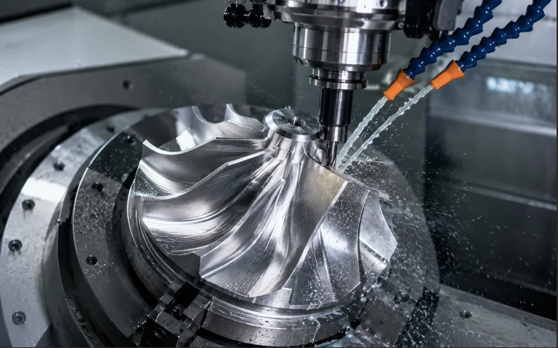
Precision Components
Dimensional and detail inspection using the 50×38 mm range.

Mold & Tooling
Complex surface deviation and wear analysis.
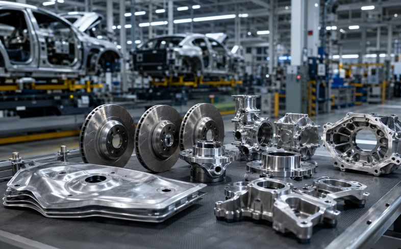
Automotive Components
Inspecting castings, housings, and molded parts.
Impellers & Freeform Parts
Full-field data capture for complex curved surfaces.

Reverse Engineering
Digitizing legacy parts without CAD drawings.

Product Development
Physical-to-digital validation in R&D laboratories.
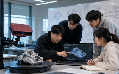
Why Engineering Teams Evaluate STScan
-
Dongguan Sentuo Technology Co., Ltd.
Real manufacturer identity based in Songshan Lake, Dongguan, with 15+ years of 3D optical measurement engineering experience.
-
In-House Technology
Both the blue-light optical hardware and the scanning/inspection software are developed around STScan proprietary architecture.
-
Verified Performance
Up to 0.005 mm measurement accuracy and <1 second single-frame capture speed.
[Measurement Test Report available upon request]
-
Pre-Purchase Support
Customers can submit part information for sample evaluation before choosing a configuration. Delivery includes a 1-year warranty and 1–2 day training.
See the Measurement Data, Not Just the Scanner
Actual point cloud and mesh results from the P500 platform.
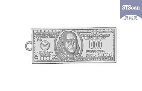
Case A: Small Precision Part
- Range Used: P500-5X (50×38 mm)
- Feature: Fine gear teeth
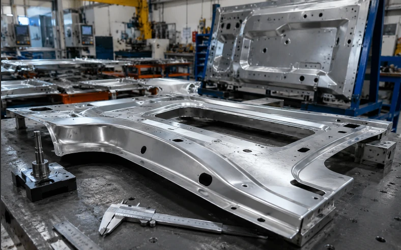
Case B: Mold Housing
- Range Used: P500-30X (300×225 mm)
- Output: Deviation Analysis Map

Case C: Complex Curved Component
- Range Used: P500-20X (200×150 mm)
- Output: High-density Mesh
Not Sure Whether P500 Can Measure Your Part? Test a Sample First.
We provide pre-purchase sample evaluation, not a commercial 3D scanning service. This ensures the P500 optical configuration matches your actual geometry and surface conditions.
See the P500 Measurement Workflow Before You Decide
Schedule a live demo to see scanner setup, measuring range selection, live scanning, alignment, mesh generation, and the inspection workflow. We can also discuss T500 vs P500 selection based on your needs.
What Determines the Cost of a P500 3D Measurement System?
Do not just compare the base scanner purchase price. The total investment depends on how you configure the platform for your specific industrial requirements.
1. Measuring Ranges
The number of ranges (choose 3 of 5) selected based on your part size variation.
2. Software & Workflow
Specific software requirements, inspection workflows, and automation needs.
3. Configuration
Accessories, training configuration, and delivery requirements.
P500 3D Measurement Scanner Specifications
| Model | P500-5X | P500-10X | P500-20X | P500-30X | P500-40X |
|---|---|---|---|---|---|
| Camera Resolution | 5 MP | 5 MP | 5 MP | 5 MP | 5 MP |
| Measuring Range | 50×38 mm | 100×75 mm | 200×150 mm | 300×225 mm | 400×300 mm |
| Typical Object Size | 5–100 mm | 50–200 mm | 100–500 mm | 150–700 mm | 200–1000 mm |
| Point Cloud Accuracy | 0.02 mm | 0.04 mm | 0.08 mm | 0.12 mm | 0.15 mm |
| Measurement Accuracy | 0.005 mm | 0.005 mm | 0.005 mm | 0.005 mm | 0.005 mm |
| Single-Frame Capture | <1 s | <1 s | <1 s | <1 s | <1 s |
| Software / Output | STScan Scanning & Inspection Software / STL, OBJ, PLY | ||||
Standard Configuration: Choose 3 of the 5 measuring ranges.
P500 3D Measurement Scanner FAQs
What is a 3D measurement scanner?
What makes P500 different from a fixed-range 3D scanner?
How accurate is the STScan P500?
Which P500 measuring range should I choose?
Is P500 a handheld 3D measurement scanner?
Can P500 be used for quality inspection?
Can P500 be used for reverse engineering?
How long does a P500 scan take?
What software is used to process P500 point-cloud data?
How much does a P500 3D measurement scanner cost?
Can I test my own part before buying P500?
How does P500 compare with a handheld 3D scanner?
Configure Your P500 3D Measurement Scanner
Share your typical part sizes and measurement requirements. Our engineers will recommend the optimal 3 measuring ranges and provide a formal configuration quote.